FPV Antenna Theory for Hobbyists: A Practical Build Log on Patch vs Omni and Optimising Range
This is a step-by-step build log aimed at hobbyists who want to understand practical FPV antenna theory while making their own mounting and setup decisions, and the aim is to compare patch and omni choices, cover polarisation, placement and how to optimise range in the field.
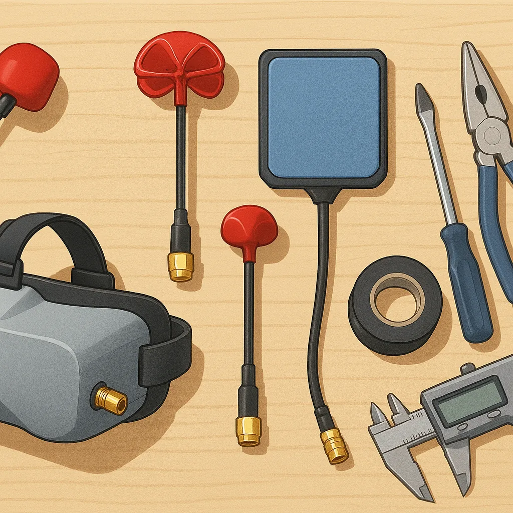
Start by gathering tools and parts and laying out the test plan so you can measure improvements as you go, and the list below is what I used for this build and bench testing.
- One RHCP patch antenna and one omnidirectional cloverleaf receiver antenna for comparison.
- Short, good quality coax pigtails with SMA or MMCX connectors, depending on your gear.
- 3D printed or laser-cut mounts and brackets to control antenna orientation and height.
- Soldering iron, heatshrink, an SWR/RSSI meter and a small spectrum checker if available.
Step 1 was to fit the patch into a simple 3D-printed cradle so its boresight was adjustable, and for reproducible tests I mounted the omni on a short stalk beside it so that both antennas could be compared without changing aircraft attitude during the first bench runs.
Building the patch mount is straightforward if you follow the dimensions printed on the antenna datasheet, and you can download my 3D mount files and measurements from my site https://watdafeck.uk for reference and to speed up your own build process.
Polarisation is the critical theory to keep in mind because mismatched polarisation delivers a major signal penalty, and for FPV video we usually use circular polarisation to reduce multipath and orientation loss while linear antennas are more common on inexpensive omnis and perform poorly when misaligned with circular antennas.
In practice you will see around 18 to 20 dB of loss when you cross a linear antenna with a circular one, so the rule is to match polarisation: RHCP to RHCP for best long-range results, and place the patch so its normal is aimed at the transmitter for maximum gain while keeping the omni higher or offset to preserve situational awareness in all headings.
Range optimisation is part hardware and part positioning, and good tips are small but cumulative: keep coax runs as short as possible to reduce loss, use low-loss RG316 or better for long runs, minimise adapter count and stubs, mount the patch clear of carbon fibre or big metallic surfaces to avoid detuning, and use diversity receivers with spatially separated antennas to tame dropouts.
Final checks included bench RSSI comparison, a low-altitude hover to validate link before full-range tests, and iterative adjustments to patch tilt and omni height to find the best trade-off between forward gain and omnidirectional coverage, and the result was a measurable increase in usable range with the matched RHCP patch plus sensible placement and cabling practices.
Follow me on: Facebook: https://www.facebook.com/watdafeck3d · Instagram: https://www.instagram.com/watdafeck3d/.
Comments
Post a Comment