Repair guides for hobbyists — a step-by-step build log for crash recovery and water damage.
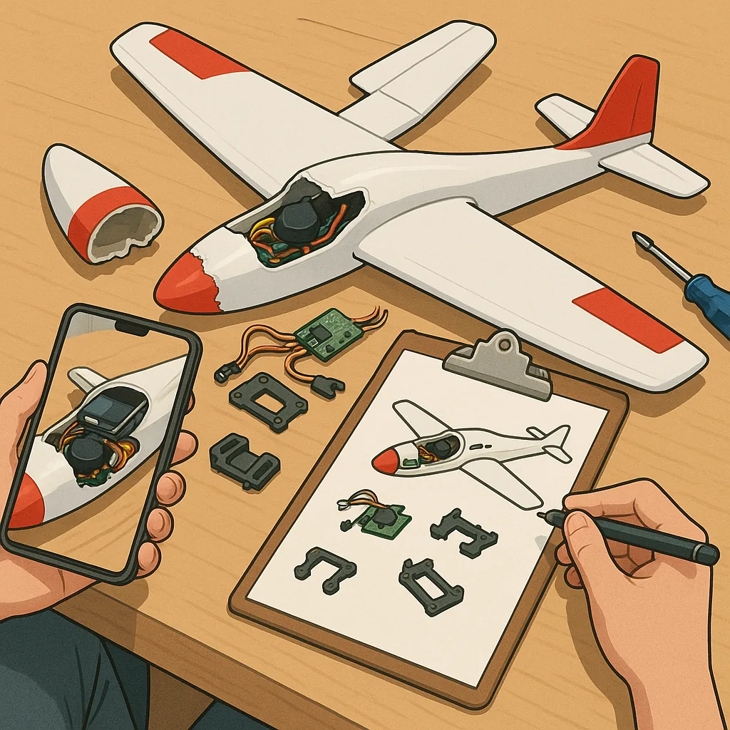
Day 1: I started this build log after a nasty weekend crash that broke the nose, snapped several mounts and soaked the receiver in sea spray. The first task was a careful triage with photos and notes so I could track what had been replaced and what might be salvageable. I took multiple close-up images of the chassis, servos and PCB with my phone and labelled them to avoid confusion during reassembly. This inventory saved time later when I ordered parts and helped me decide which components would be repaired rather than replaced based on cost and availability.
Day 2: Safety and preliminary disassembly came next, beginning with battery removal and a continuity check to rule out short circuits. I always remove LiPo packs before any work and make sure to discharge any capacitors where necessary so there is no stored energy in the system. I then removed propellers and motors to access mounts and servo linkages while keeping screws and small parts in labelled tubs so nothing went missing. With the airframe open I examined wiring for chafing and pushed connectors apart cleanly to avoid stressing pins.
Day 3: Mount repair focused on parts that were cracked rather than pulverised, and I chose to 3D print replacement mounts for exact fit and alignment. I measured original parts carefully and modelled reinforcements with a small ribbed gusset to spread load across the chassis, using PETG for a good balance of strength and flexibility. For load-bearing areas I bonded thin carbon rods into channels with epoxy for extra stiffness and used countersunk stainless screws to avoid local crushing. Test-fit is critical so I assembled the repaired section dry first and adjusted hole positions before final fastenings to ensure correct geometry and control surface alignment.
Day 4: Servos and stripped fixings required a different approach because you can often rescue cheap servos with a modest amount of surgery. I opened each servo in turn and inspected gear teeth for wear or missing cogs and swapped in spare gears where available, taking note of gear mesh and bearing play during reassembly. For stripped horn mount holes I used a tiny brass insert or a dab of two-part epoxy reinforced with a short M2.5 screw to regain thread retention when the plastic had failed. If the output spline was damaged beyond repair I replaced the whole servo mechanism, but in several cases reinforcing the horn with a thin steel washer and a bead of cyanoacrylate allowed safe flight for another season.
Day 5: Water damage recovery was the slowest part and involved patient cleaning, drying and testing to avoid frying electronics when power was restored. I disassembled soaked modules and rinsed corroded areas with distilled water followed by isopropyl alcohol to remove salts, then brushed PCB tracks gently with a soft toothbrush and alcohol to lift deposits. After cleaning I placed the boards in front of a fan with desiccant for 48 to 72 hours rather than using high heat that can warp connectors or batteries. Once dry I checked continuity, replaced any corroded connectors, and powered up systems incrementally while monitoring current draw and temperatures. For reference and printable mount designs that helped with reassembly you can find more build logs on the WatDaFeck blog at WatDaFeck.
Final assembly and test flights were done progressively, starting with bench calibration of servos and ESCs and moving to short low-altitude hops to confirm control authority and vibration levels. I retightened every fastener after the first hover and inspected for new stress cracks that can appear after the initial repair. Preventative measures taken for the future included using conformal coating on vulnerable electronics, fitting sacrificial foam or bumpers at mount points, and keeping a small repair kit of spare screws, brass inserts and a basic set of 3D printed mounts in the workshop. The overall job saved the model at a fraction of the replacement cost and taught a lot about designing for serviceability.
Follow me on: Facebook: https://www.facebook.com/watdafeck3d · Instagram: https://www.instagram.com/watdafeck3d/.
Comments
Post a Comment