Troubleshooting RC Tools: Servo Testers, Watt Meters, Torque Drivers and Alignment Jigs
Good tools make good builds, but even the best kit can be hard to trust when something goes wrong, so this guide focuses on practical troubleshooting for the core RC workshop tools that save you time and frustration. I will walk through common symptoms, quick diagnostic checks and sensible fixes for servo testers, watt meters, torque drivers and alignment jigs, with an emphasis on repeatable checks that hobbyists can do with basic equipment. The aim is to get you diagnosing fault sources rather than replacing parts at random, and to encourage a methodical approach that protects servos, ESCs, airframes and your wallet.
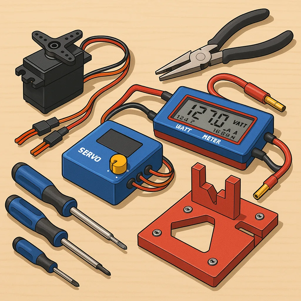
Servo testers are one of the most useful pieces of kit, but they are also a frequent source of confusion when a servo behaves oddly, refuses to centre or jitters under load. Start by isolating power and signal: connect the tester to a known good battery or regulated BEC and a single servo out of the airframe to remove mechanical binding as a variable. If the servo still jitters, check the connector polarity and the voltage delivered to the servo under both idle and active positions, because low voltage or brownouts often mimic electronic faults. Use the tester’s sweep and centre functions to look for dead spots in the range, and try another servo on the same channel to determine whether the issue is the servo or the tester output signal. If a digital servo hunts at a specific PWM frequency, try a different tester or a simple microcontroller PWM output to confirm the frequency compatibility, and visually inspect gears for slop or stripped teeth before condemning the electronics.
Watt meters provide essential current and power readings for motors and power systems, but many problems come from measurement setup rather than the device under test. If a watt meter reads implausibly high or low, ensure it is placed in-line with the positive supply lead and that the meter’s voltage and current ranges are not being exceeded, since clipping will give nonsense figures. Check the shunt connections for corrosion or loose crimps and test the meter with a known resistive load such as a power resistor and a regulated supply to verify calibration. Beware of rapid fluctuations caused by ESC telemetry or regenerative currents during motor braking, and use a smoothing or averaging feature if present for more meaningful figures. Temperature can shift readings, so allow the meter to settle thermally during longer runs and avoid measuring at the extremes of its specification for consistent results.
Torque drivers and alignment jigs are where torque control and mechanical geometry meet, and mistakes here cause stripped threads and misaligned drives that ruin otherwise well-matched systems. If screws loosen or strip, first confirm the torque driver is correctly calibrated by checking it against a torque calibration gauge or a trusted reference tool, and replace worn bits that slip and round heads. Use the correct torque settings for aluminium, steel and composite materials and remember that threadlocker and locking washers change the effective clamping force, so adjust torque accordingly. Alignment jigs sometimes introduce new problems when they are themselves mis-set, so verify jig references with a straight edge or a dial indicator, shim where necessary and perform final checks with the actual component fitted rather than relying entirely on the jig geometry alone.
- Check power first: voltage, polarity and connection integrity.
- Swap components to isolate whether the fault is tool or part related.
- Use known loads or reference tools to verify measurement instruments.
- Maintain torque bits and inspect mechanical linkages for binding.
To keep problems manageable, adopt a short checklist routine before each maiden or repair session and keep documented readings for repeatability, and if you want downloadable checklists, wiring diagrams or templates to print for your workshop see WatDaFeck for companion resources that complement this troubleshooting approach. Regular maintenance such as cleaning connectors, checking solder joints, and verifying torque driver calibration every few months will prevent the majority of field failures, and keeping a small set of bench tests for servos, ESCs and battery packs will allow you to compare current behaviour with baseline performance quickly and confidently.
Follow me on: Facebook: https://www.facebook.com/watdafeck3d · Instagram: https://www.instagram.com/watdafeck3d/.
Comments
Post a Comment