CAN bus for RC: a hands-on MAVLink and UAVCAN build log.
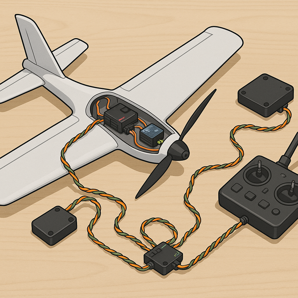
This is a step-by-step build log showing how I moved an RC airframe from a tangle of PWM wires to a tidy CAN bus system, concentrating on MAVLink integration, UAVCAN sensors and making the servo bus dependable for field use.
My objective was to reduce wiring complexity, get sensor telemetry on the ground station via MAVLink and create a robust servo solution that survives vibration and wet conditions, and I kept reliability as the primary design criterion.
For the build I gathered a compact flight controller with CAN support, UAVCAN-capable barometer and GPS modules, a couple of UAVCAN ESCs and either CAN-capable servos or smart ESCs with servo outputs, plus decent connectors and tools.
- Flight controller with CAN and MAVLink support, such as a Pixhawk-style controller or similar UAV autopilot.
- UAVCAN sensors: barometer, GPS, compass and optional airspeed sensor supporting UAVCAN or a CAN bridge module.
- CAN ESCs or CAN servos depending on model, and a power distribution board or battery connectors rated for servo current.
- Cable: twisted pair for CAN H and CAN L with suitable wire gauge, good quality crimp connectors, heatshrink and a couple of 120 ohm terminators.
- Tools: decent crimper, multimeter, screwdriver set and an oscilloscope if you have one to check bus integrity during commissioning.
Wiring reliability was the part I was obsessive about, and I used a short, daisy-chained CAN bus with twisted pair for H and L to avoid stubs and reflections, fitted 120 ohm termination at each physical end of the main run and kept high-current servo wiring separate from the CAN pair to reduce noise coupling.
For my build I documented connector choices, crimp quality checks and photographs on WatDaFeck so that others can copy the same reliable wiring layout and inspection steps without guessing what I did at each joint.
Integrating MAVLink and UAVCAN required a couple of configuration steps, and I used the flight controller to act as a MAVLink endpoint while letting UAVCAN handle sensor nodes directly, giving the ground station access to sensor telemetry without extra converters and saving a lot of wiring complexity during installation.
Servo buses are where reliability and current handling intersect, and my approach was to keep CAN for signalling and use separate, well-soldered power rails and short servo leads, add bulk decoupling capacitors at power entry points and ensure ESCs or servos expose telemetry over UAVCAN so the controller can monitor current draw and temperatures in flight for safety.
My step-by-step execution was as follows: first I built the CAN backbone on the bench and verified continuity and correct termination with a multimeter, second I mounted and configured UAVCAN sensor nodes one at a time and assigned unique node IDs, third I connected the flight controller and verified MAVLink telemetry for each sensor through the ground station, fourth I replaced PWM servo lines with CAN servos or connected servo outputs to CAN-enabled ESCs and carefully tested each control surface on the ground, and fifth I performed a set of bench power tests followed by short hover or taxi tests to verify thermal behaviour and wiring integrity before any full flights.
In the end the aircraft was quieter in the wiring bay, the ground station received richer telemetry via MAVLink thanks to UAVCAN sensors and the servo bus behaved predictably even under load, and the lessons about termination, good crimping and separating power from signal cabling are the ones I will repeat on every future build.
Comments
Post a Comment