Building a Hotwire CNC for Foam Airfoils and Wing Cores: A Step-by-Step Log
I decided to build a hotwire CNC specifically to cut accurate airfoils and wing cores for model aircraft, and this article is a step-by-step log of that build so other hobbyists can follow the process and avoid the mistakes I made along the way.
The project started with the basic requirements: a rigid frame sized to fit the largest wing core I wanted to make, a reliable wire heating and tensioning system, stepper-driven axes for repeatable motion, and software to turn airfoil coordinates into stacked cross-sections. If you want to see more of my builds and downloadable templates, you can visit my project page at https://watdafeck.uk to grab example G-code and airfoil files.
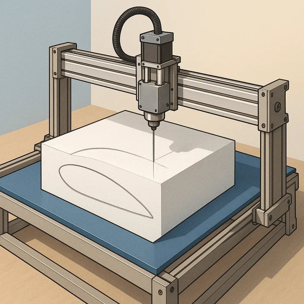
I chose a 1.2 metre by 0.6 metre aluminium profile frame for stiffness and corrosion resistance, and mounted a hardwood wasteboard to keep foam scraps under control. The Y-axis is two linear rails with a carriage that carries the hotwire gantry, while X travel is provided by a belt-driven rail that positions the wire vertically to sweep cross-sections. I used NEMA 17 steppers for all axes because they offer enough torque and are economical for hobby builds.
The hotwire assembly is simple but needs attention to detail because safety and accuracy both depend on it. I made the wire holder from stainless steel tubing and used 0.5 mm nichrome wire stretched between two ceramic-insulated terminals. For reliable tension I fitted a small turnbuckle on one end and a spring-loaded idler on the other, which prevents the wire from slackening as it heats. The MOSFET-based PWM controller runs from a 24 V supply and gives smooth power control, which helps when cutting different foams like EPS and XPS without burning the edges.
Generating toolpaths for airfoils and wing cores is the part that turned this into a CNC project rather than a jig. I downloaded airfoil coordinate .dat files and wrote a small script to interpolate sections along the span to produce vertical slices, then exported those slices as linear G-code suitable for a GRBL controller. The workflow is: pick an airfoil, define span and chord distribution, slice into sections, generate G-code for each slice, and feed the code to the machine while stacking foam sheets on the bed. The stack-up method gives precise wing cores with consistent internal shear web positions and allows composite skins to be fitted later.
Finishing the cores is straightforward but important for performance. After cutting I lightly sanded the surfaces to remove sag and chamfered the leading and trailing edges to match the template radii, then glued multiple halves together with contact adhesive and pin clamps. If you need a template for hand finishing or jigging ribs, cut a thin ply template from the same G-code and check it against the airfoil coordinates to serve as a reference. Key safety and quality tips include cutting in a well ventilated area or outdoors, using a respirator rated for polymer particulates, and testing one scrap slice before committing an entire wing core to the process.
Common pitfalls I encountered were wire breakage from over-tensioning, foam melt from excessive power, and drift from a loosely mounted stepper carriage, and all were resolved by modest design adjustments and a disciplined test routine. For hobbyists, a home-built hotwire CNC is an affordable way to produce precise airfoils and wing cores if you pay attention to mechanical rigidity, wire control, tooling code, and safe working practises.
Follow me on: Facebook: https://www.facebook.com/watdafeck3d · Instagram: https://www.instagram.com/watdafeck3d/.
Comments
Post a Comment