Workshop Build Log: Making Essential RC Tools — Servo Tester, Watt Meter, Torque Driver and Alignment Jigs.
Workshop Build Log: Making Essential RC Tools — Servo Tester, Watt Meter, Torque Driver and Alignment Jigs.
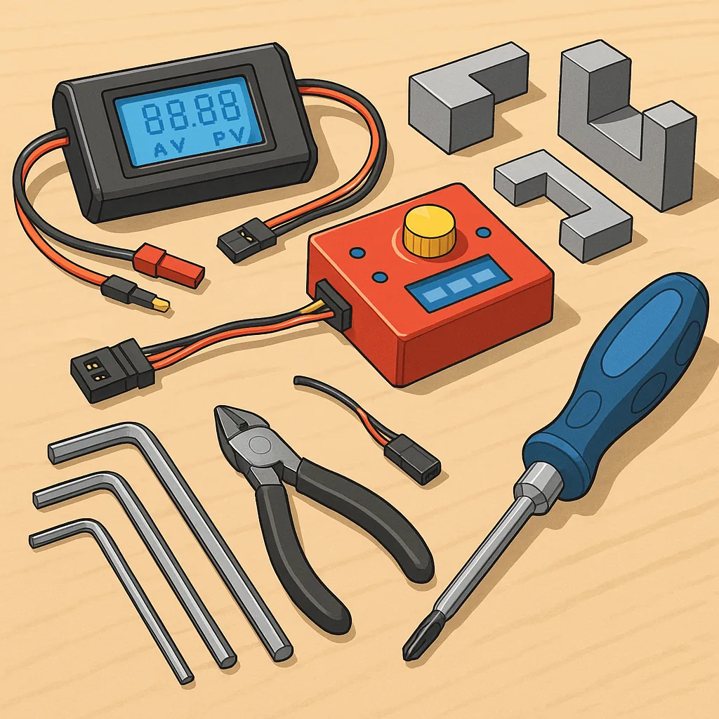
This build log records a practical, step-by-step approach to creating four workshop essentials for RC hobbyists: a servo tester, a watt meter, a torque driver and a set of alignment jigs for clean assembly and reliable setups.
Before I started I gathered parts and checked my tools, and the short list below kept the project tidy and efficient.
- Arduino Nano or ATtiny85 board, three-pin servo sockets and a rotary pot for the tester.
- INA219 or INA226 breakout, a low-ohm shunt resistor, 0.96" OLED display and XT60 connectors for the watt meter.
- Precision screwdriver bits, a calibrated torque adapter or spring assembly and a small bench vise for the torque driver.
- PLA or PETG filament for 3D printed jigs, M3/M4 dowels and small clamps for alignment fixtures.
I began with the servo tester as it is the quickest to assemble and the most immediately useful for bench work, and I wired an Arduino Nano with a potentiometer and a three-pin servo header to create a sweep and centring function.
Step one for the tester was writing a simple sketch to output variable PWM across 1 to 2 milliseconds and add a centre and neutral button, and I enclosed everything in a small 3D printed box with a recessed pot and labelled connectors to avoid confusion during busy builds.
The watt meter came next and required a little more care because of the shunt resistor and calibration, and I mounted the INA219 board on a small PCB with an OLED display and XT60 sockets so I could measure voltage, current and track power draw in flight-simulated loads.
Calibration for the watt meter was straightforward using a trusted bench meter, adjusting the shunt value in the library and validating at a few points up to the expected peak current, and mounting the display where it is readable during ground tests makes diagnosing power issues much faster.
For the torque driver I opted to modify a cheap torque adapter by fitting a collet and calibrating the release with a small digital torque wrench and a threaded test rig, and the key was setting the click point in small increments so M2 and M3 fasteners get consistent clamping without stripping soft alloy parts.
Making alignment jigs was the final stage and likely the most time-saving for repeat builds because I printed a set of arm holders and motor mount templates that match common frames, and I used the servo tester and watt meter together during final checks to ensure no binding or current spikes before finishing a model and you can see the CAD files and finished photos on my project page at https://watdafeck.uk.
Lessons learned were simple but valuable, and they include taking time to label connectors, keeping a small calibration log for the watt meter and torque adapter, and printing a few spare jigs to accommodate different frame geometries so future builds are faster and more reliable.
Comments
Post a Comment