Range testing for hobbyists: practical tips on antennas, ELRS tuning, noise and filtering.
Range testing is one of the most useful exercises a radio-controlled hobbyist can perform, because it reveals real-world limitations that bench testing will not show. A careful, methodical approach reduces the chance of losing a model during flight and helps you optimise both performance and safety. The following guide focuses on antenna placement, tuning ExpressLRS settings, reducing electrical noise and improving filtering for reliable long-range operation.
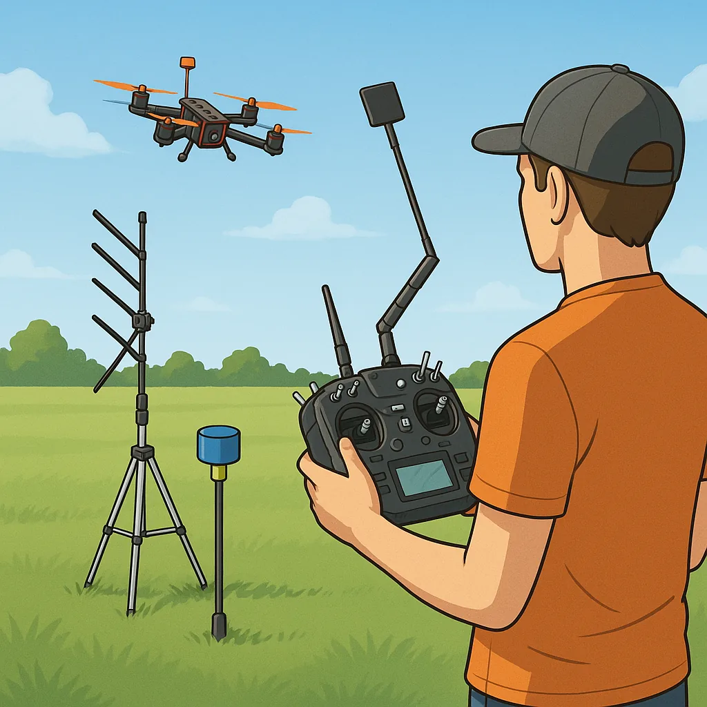
Antenna placement is the single most impactful adjustment you can make without changing hardware, so start there and treat it as an experiment rather than a one-off setup. On the receiver use a diversity arrangement when possible, and keep the two antennas at roughly 90 degrees to one another so one will almost always have a better take on the polarisation. For small foam models route antennas away from carbon fibre and power-hungry components, secure them with heatshrink or soft tubing to prevent chafing, and aim to keep them on different planes so they are not shadowed by your airframe during common manoeuvres.
When tuning ExpressLRS, remember that packet rate and transmit power are a trade-off between latency and raw range, so adjust them according to your mission rather than always running max power. Lower packet rates and higher output power will generally increase range, but at the cost of responsiveness and battery life, so perform comparative tests at realistic flight heights and orientations. Also use telemetry to log RSSI and link quality as you adjust settings, since subjective "feels good" assessments can miss marginal link degradation during a long test.
Electrical noise from ESCs, motors and wiring often mimics range loss, so address noise reduction before assuming your radio needs more power. Use twisted pairs for motor and servo wiring, keep high-current loops as short as possible, and fit small ferrite beads on signal lines close to the flight controller and receiver to kill high frequency interference. If you experience spurts of packet loss that align with throttle use or motor RPM changes, investigate shared grounds and return paths rather than immediately increasing transmitter power.
Fit proper filtering on power rails to give the receiver and flight controller a clean supply and reduce radiated emissions from switching electronics. A combination of electrolytic and ceramic decoupling capacitors close to the receiver and flight controller helps stabilise voltages, while a common-mode choke on the main battery leads will reduce conducted noise into the rest of the airframe. For video systems and telemetry consider an LC filter or a dedicated power filter module, and use grounded metal mounting points where possible to provide a reliable RF reference without shorting antenna fields.
Plan a repeatable range test routine so your comparisons are meaningful and documented, and always obey local regulations and safety practises when transmitting at higher power. Start each test at low power in an open field, walk or drive to increasing distances while watching RSSI and link quality, and perform orientation checks by rotating the model relative to the ground station to note dead spots. Keep a log of antenna configurations, ELRS settings, filtering changes and environmental conditions so you can identify correlations, and for further build guides and troubleshooting tips visit WatDaFeck for additional resources and examples.
Follow me on: Facebook: https://www.facebook.com/watdafeck3d · Instagram: https://www.instagram.com/watdafeck3d/.
Comments
Post a Comment