FPV Antenna Theory for Hobbyists: Patch vs Omni, Polarisation, Placement and Range Projects.
Good antenna choices will transform your FPV experience more than most upgrades, so this roundup collects practical project ideas and theory that are useful for hobbyists, makers and racers alike.
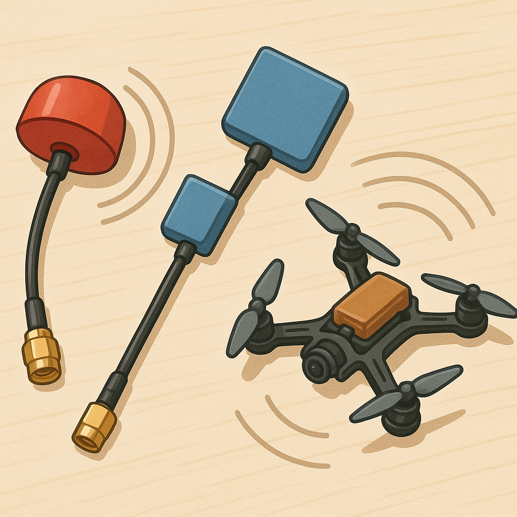
Understanding patch versus omni is the first step in antenna decisions because the two serve different roles and are often used together for best results. An omni antenna radiates and receives in nearly all directions with relatively low gain, which makes it forgiving of orientation and useful on a race quad that is constantly rotating. A patch antenna is a directional device with higher gain and a focused beam, ideal for extending range on long flights when you can point the patch towards the aircraft, such as on a ground station or goggles. Expect trade-offs in size, weight and beamwidth when choosing between them, and consider making a small test jig to compare a commercial patch and omni on your setup for real-world data collection.
Polarisation is another often-misunderstood factor that explains mysterious signal drops in the field, because mismatched polarisation creates large losses even with high-gain hardware. Linear polarisation is common on simple omnidirectional antennas, while most modern FPV video systems favour circular polarisation, typically LHCP or RHCP, because it reduces multipath nulls and tends to handle reflections better. Always match polarisation between transmitter and receiver to avoid cross-polarisation loss, and try diversity receivers or orthogonally mounted antennas if you need better consistency across different flight attitudes.
Placement and mounting are the low-cost optimisation steps that give the biggest practical gains, so treat them as an experiment rather than guesswork. Keep receiving and transmitting antennas physically separated to reduce on-board self-blocking and RF coupling, and avoid placing antennas directly behind carbon-fibre plates which can attenuate signals significantly. For patches, provide a stable mount and a clear forward view and consider a small ground plane or backing plate to get the intended radiation pattern. For omnidirectional sticks, keep them vertical and as high as practical on the craft, and test cable length and connectors to limit loss from cheap coax or tight bends.
Range optimisation is a system-level task and combines antenna choice, polarisation matching, feedline quality and sensible power use, plus legal considerations about transmitter strength. Use low-loss coax or pigtails and quality connectors to protect the signal between antenna and radio, measure VSWR or use a known good antenna to sanity-check performance, and prefer circular polarised patches on the ground with an omni on the quad for a reliable combination. For clever projects, experiment with simple low-noise amplifiers, directional tracking mounts for your patch or a telemetry-linked signal strength logger to map the actual link envelope over a course.
Project ideas to put this theory into practice include building a DIY patch from FR4 or 3D-printed substrate, making a lightweight omni based on small dipole elements, constructing a motorised antenna tracker, fabricating a goggle patch mount with adjustable tilt, and creating a handheld RSSI logger to record range tests for different polarisation and placement setups.
If you want step-by-step write-ups, parts lists and example builds to start any of these projects, check the WatDaFeck project hub at https://watdafeck.uk for guides and inspiration.
Follow me on: Facebook: https://www.facebook.com/watdafeck3d · Instagram: https://www.instagram.com/watdafeck3d/.
Comments
Post a Comment