CAD Design for Hobbyists: A Step-by-Step Build Log in Fusion 360 and Onshape.
I started this project with a simple brief: design a small modular camera mount that snaps together and can be printed on my hobby FDM printer, and I kept the process as a build log so I could reproduce the decisions later on for other parts and projects.
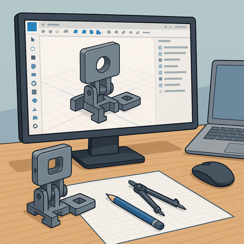
The first step was choosing the CAD platform and setting up the file structure, and I worked in both Fusion 360 and Onshape to compare workflows and collaboration features.
Sketching the core geometry began with parametric constraints and named parameters so I could easily change hole sizes and wall thickness across the model, and that made the later tolerance adjustments straightforward.
When it came to tolerances and fit I treated the design like a small engineering problem and documented the clearances I would test with real prints, and I recommend starting with a few common test values and iterating from there for your particular printer and material.
To help with choosing sensible starting points I ran a short tolerance matrix and printed the pieces progressively, and the set of test fits I used is listed here for reference.
- Press-fit peg to hole: start with +0.1 mm clearance and adjust per printer behaviour.
- Sliding fit: aim for 0.15–0.3 mm clearance depending on filament and layer height.
- Snap-fit: design with a flex allowance and plan for 0.2 mm overall tolerance reduction if parts are thin.
Assemblies and motion were explored in both packages by using Fusion 360 joints and Onshape mate connectors, and I kept subassemblies small so I could test mating conditions quickly and swap parts without breaking references.
Printing for fit required a few practical tricks such as printing orientation to reduce dimensional error on critical faces, adding test pins and sockets to confirm clearance, and exporting STLs with enough facet resolution before slicing to avoid geometry loss, and I kept a log of the prints and measurement adjustments on my blog at WatDaFeck.
From the build log I learned to lean on parameters in Fusion 360 and the version history in Onshape to backtrack as needed, and the final practical steps were to calibrate extrusion multiplier, reprint adjusted samples, and update the master model with the final measured offsets so new copies fit first time.
Follow me on: Facebook: https://www.facebook.com/watdafeck3d · Instagram: https://www.instagram.com/watdafeck3d/.
Comments
Post a Comment