CAN bus for RC: a safety overview for hobbyists
CAN bus systems are becoming common in radio-controlled aircraft and multirotor projects because they offer robust, multi-node communication and resilience to certain types of noise and packet loss. Hobbyists should treat CAN as a critical subsystem rather than a convenience, because failures in wiring, grounding or node configuration can create unsafe behaviour in flight systems. This overview explains the key hazards and practical mitigations so you can plan safer builds and bench tests.
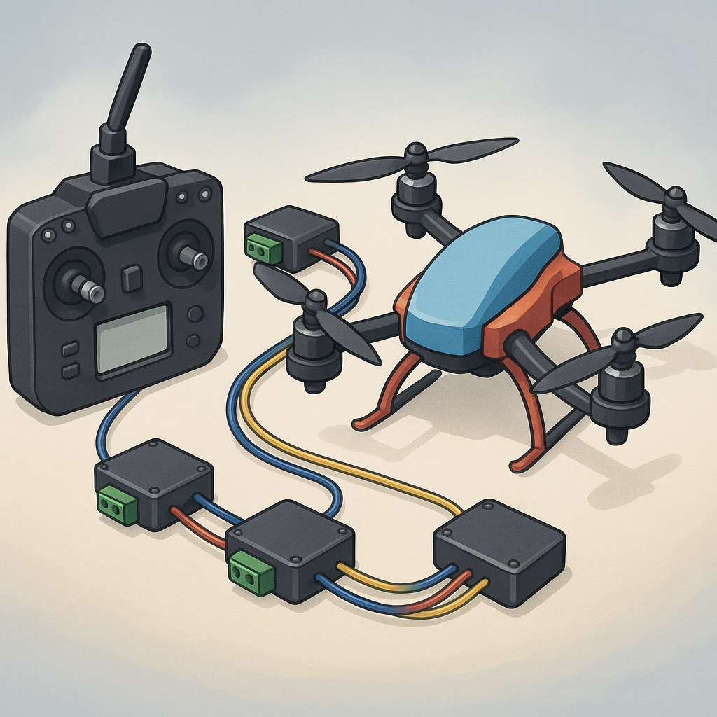
Wiring reliability is the single biggest contributor to CAN bus safety, and attention to physical installation pays dividends. Use quality twisted-pair cable for the CAN high and CAN low conductors, keep the pair short and away from high-current motor or battery wiring, and fit proper strain relief and IP-rated connectors when you fly in damp or dusty conditions. Make sure both ends of the bus are terminated with 120 ohm resistors and verify continuity and absence of shorts before power-up, because intermittent solder joints or crushed wires are common failure modes in rough handling.
UAVCAN sensors add great functionality but introduce new configuration and firmware risks that need controlling. Always check node IDs and firmware versions, and perform a bench calibration of any magnetometers, IMUs or barometers before a first flight to reject a faulty sensor. Remember that UAVCAN v0 and Cyphal (UAVCAN v1) are not interchangeable, so confirm compatibility between your flight controller and sensor modules. If you want practical wiring examples and tutorials that are specific to small-scale builds, see WatDaFeck for articles on sensor mounting and harness preparation.
MAVLink remains the standard telemetry and command protocol for many autopilots, and interactions between MAVLink and CAN-based devices deserve careful thought for safety. Avoid routing command channels through untested bridges or converters during critical phases of flight, and set robust failsafe behaviours in your flight controller so loss of telemetry or a noisy CAN bus results in a predictable outcome such as a return-to-launch or controlled land. When integrating ESC telemetry or CAN-attached GPS units, monitor CPU and bus utilisation to prevent latency spikes that could delay control loops.
Servo buses are especially prone to power-related issues on small models, and mechanical loads can create large transient currents that upset logic-level devices on the same supply. Never run multiple high-torque servos from a single undersized BEC, use separate supply lines with appropriate gauge, and include fuses or current-limiting measures where a jammed servo could draw a stall current. Add decoupling capacitors close to high-draw consumers, keep signal wires for servos separate from CAN pairs to reduce cross-talk, and perform ground-fault and short-circuit tests on the bench to detect wiring mistakes before flight.
Before you first flight with a CAN-enabled system, carry out a simple checklist that includes visual inspection of all connectors, a bus scan to confirm node IDs and uptime, validation of termination resistors and a powered smoke test on the bench for a short interval. Log telemetry during a tethered hover or taxi test and review it for unusual CAN error frames or intermittent disconnects, and if anything looks marginal, fix the wiring or replace the module before flying. Following these steps will reduce the risk of in-flight surprises and keep your builds reliable and safe.
Follow me on: Facebook: https://www.facebook.com/watdafeck3d · Instagram: https://www.instagram.com/watdafeck3d/.
Comments
Post a Comment